4. GENERAL METHODS OF CALCULATION OF HEAT EXCHANGERS
4.1. Method of factor F
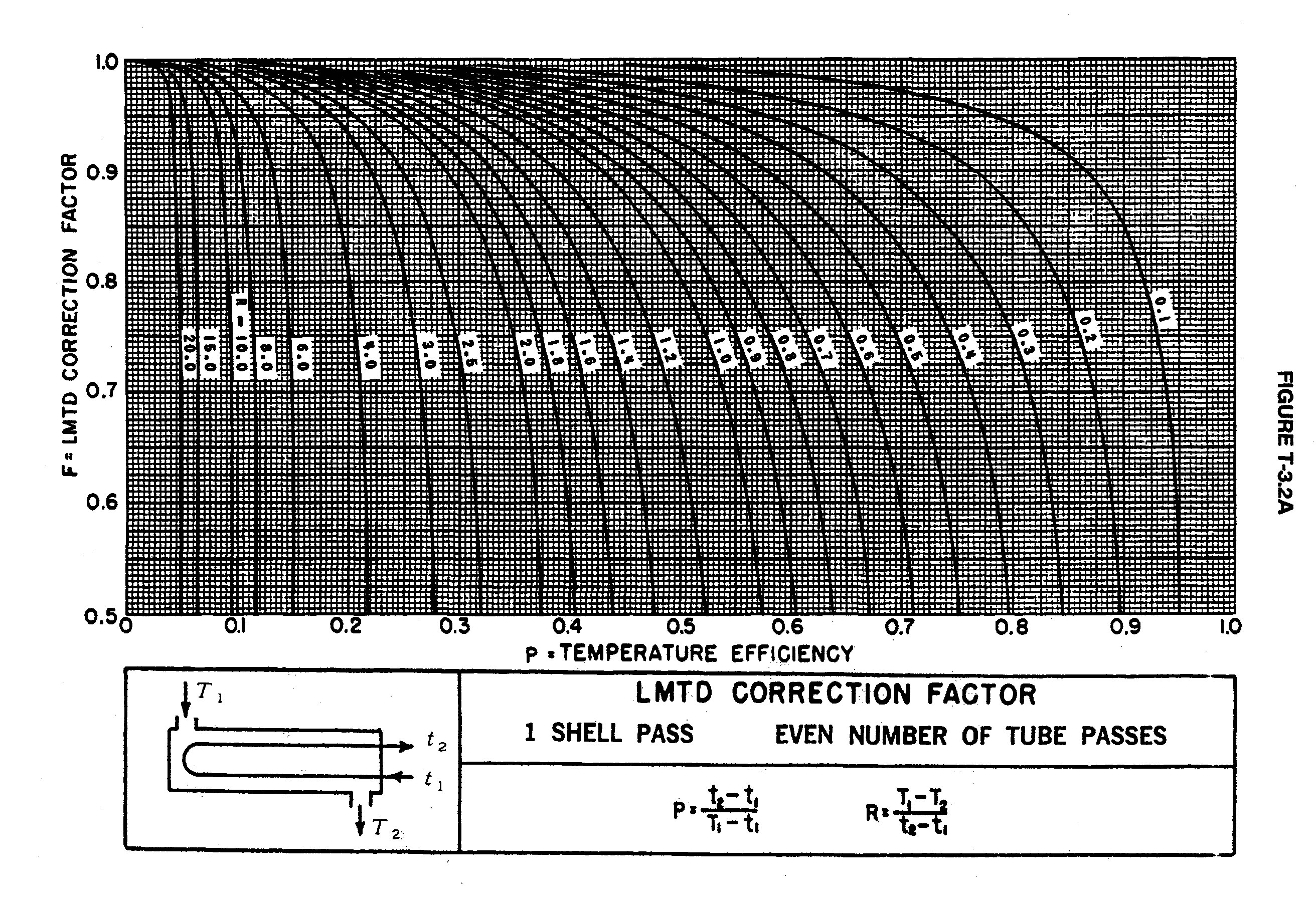
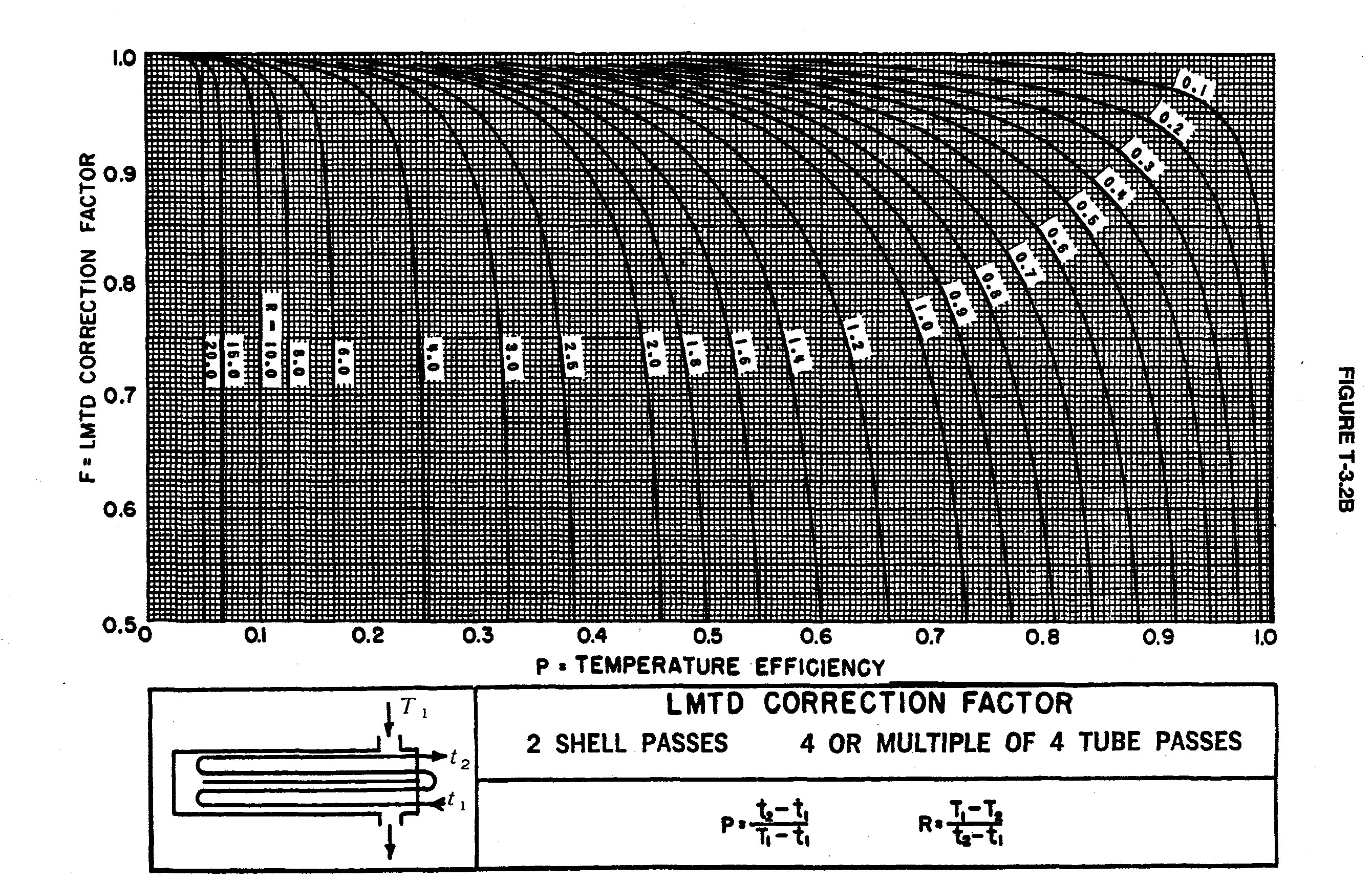
4.1.1. Graphs of factor F for different equipment
Here are the different graphs of factor F for different equipment (click on the image you can see well):
-1 shell pass and even number of tube passes :
- 2 shell passes and 4 or multiple of 4 tube passes:
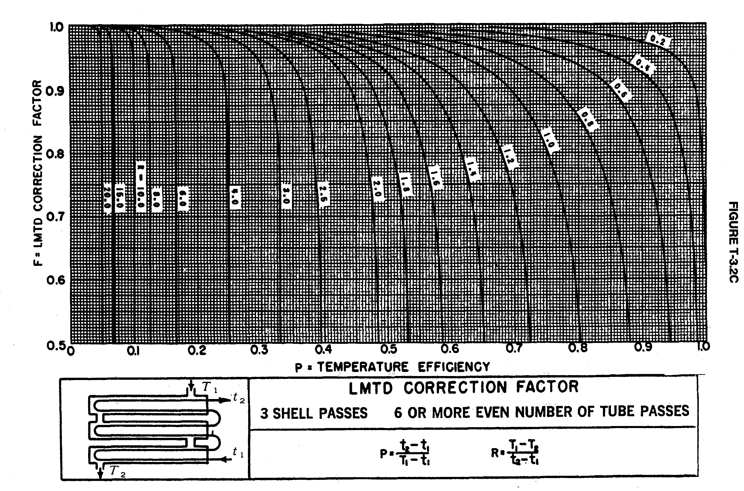
When the configuration is different from the previous two graphs, one can use the following graphs (click on the image you can see better)
- 3 shell passes and 6 or more even numbers of tube passes:
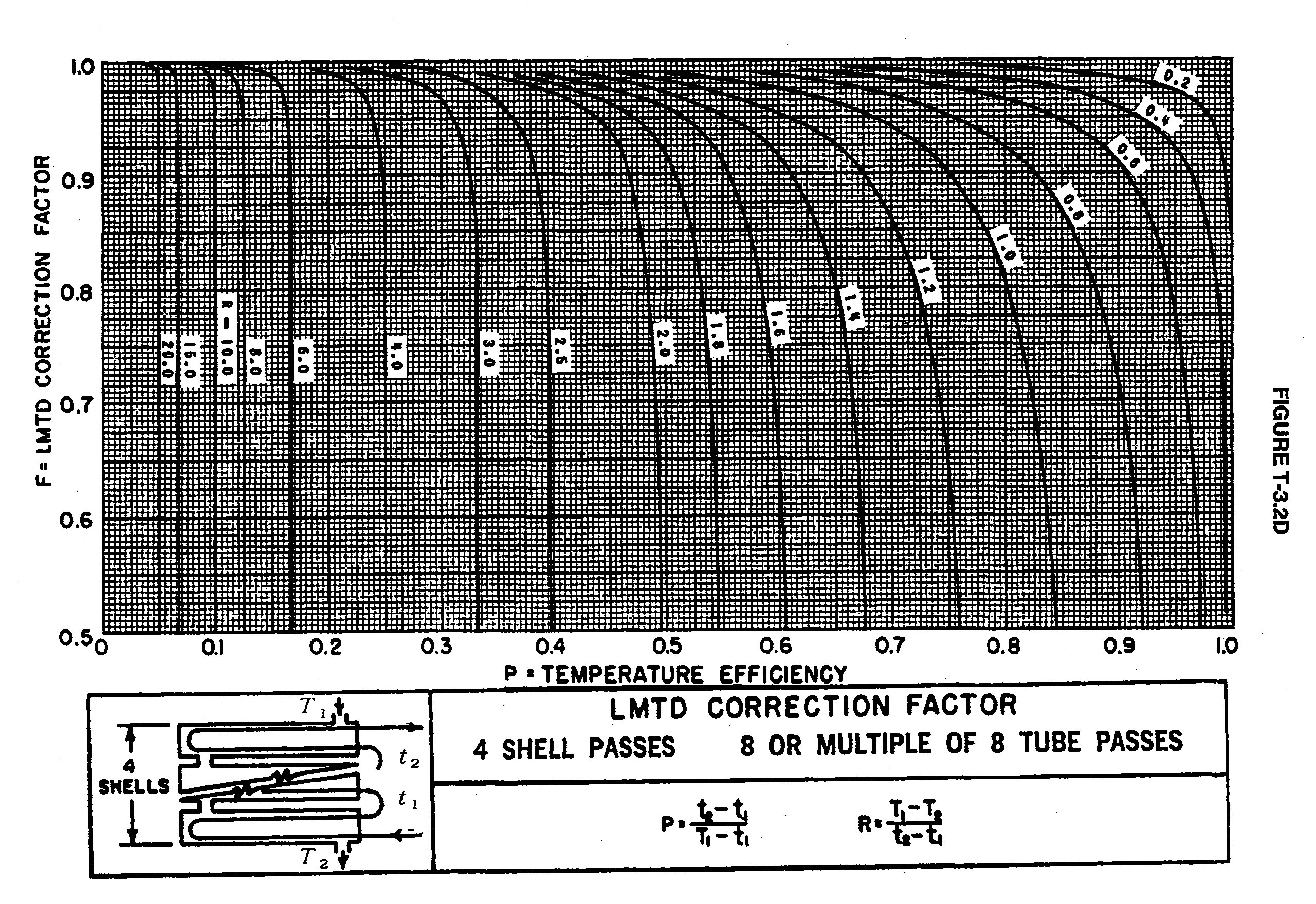
- 4 shell passes and 8 or multiple of 8 tube passes:
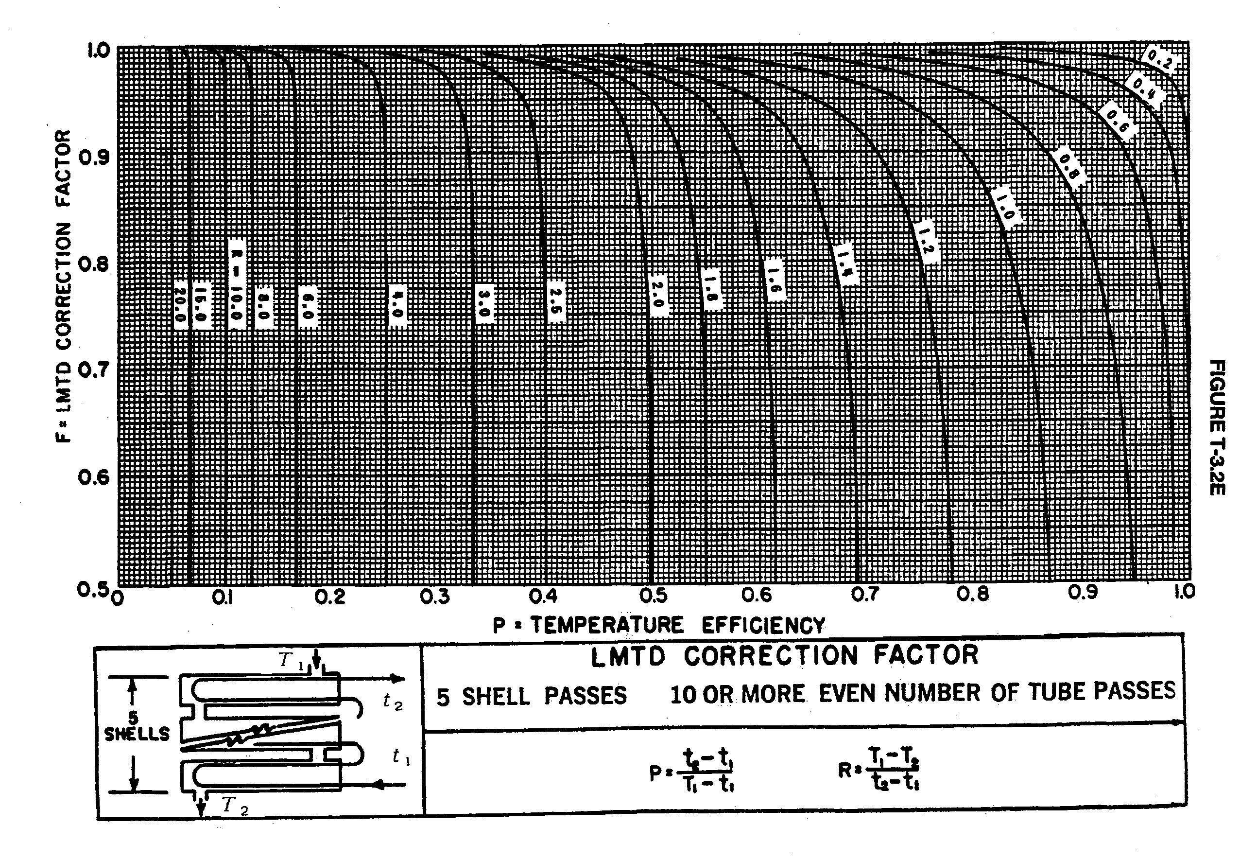
- 5 shell passes and 10 or more even numbers of tube passes:
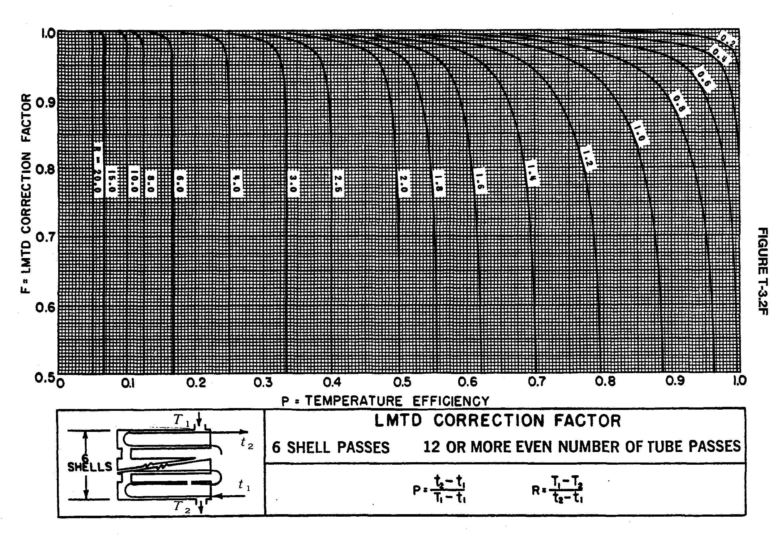
- 6 shell passes and 12 or more even numbers of tube passes:
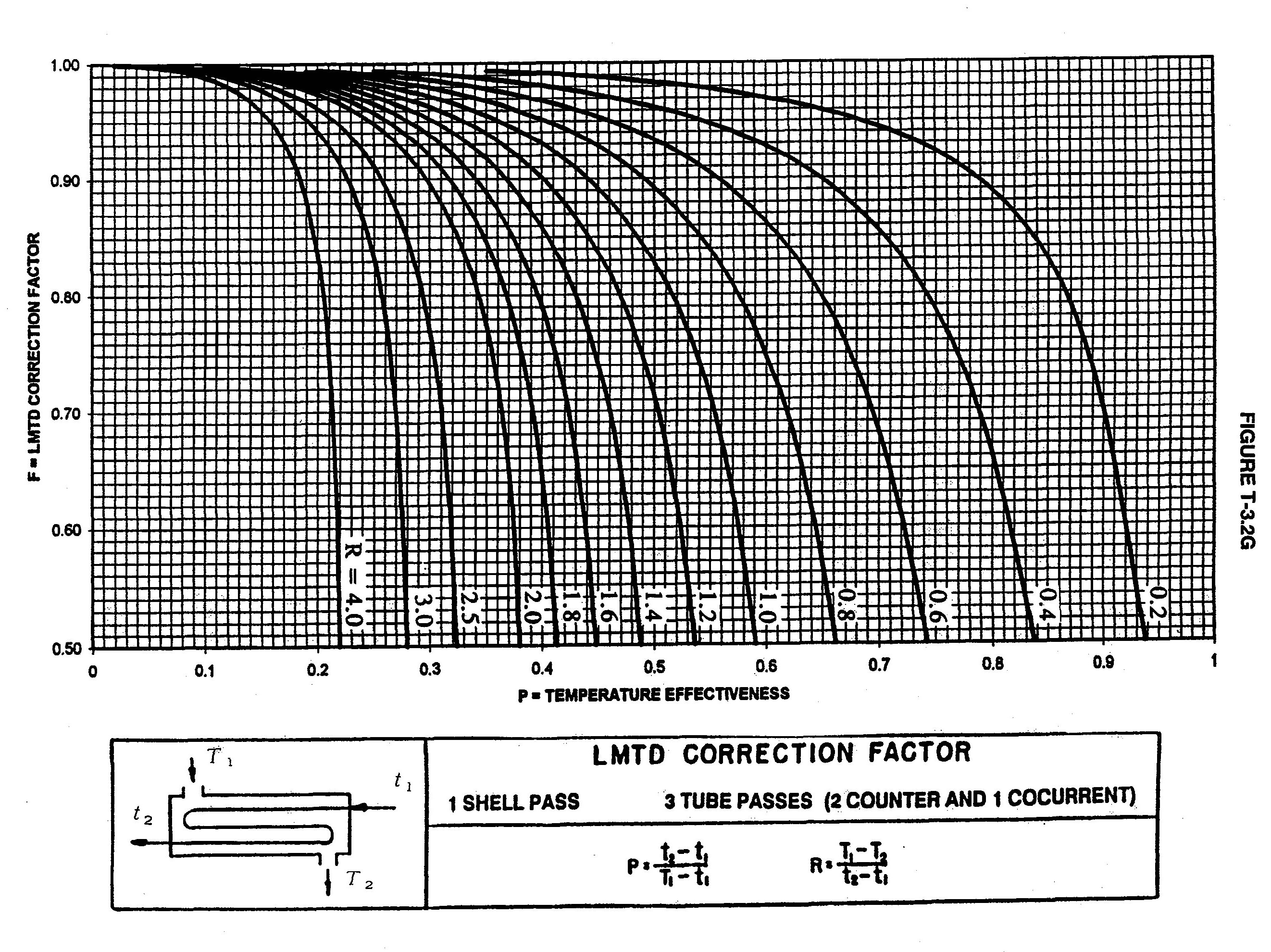
- 1 shell pass and 3 tube passes ( 2 parallel and 1 counter):
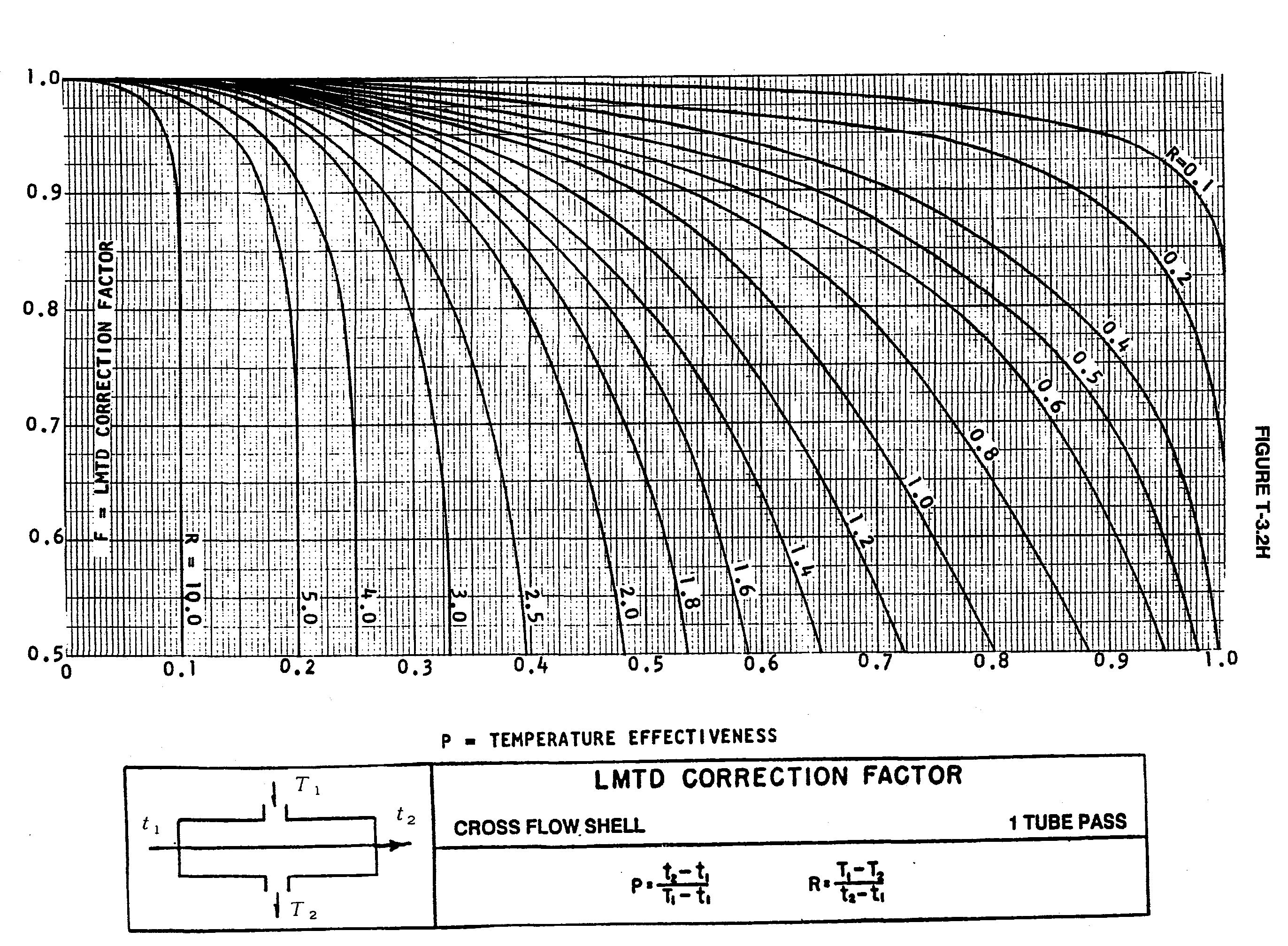
- 1 shell pass (cross flow) and 1 tube pass:
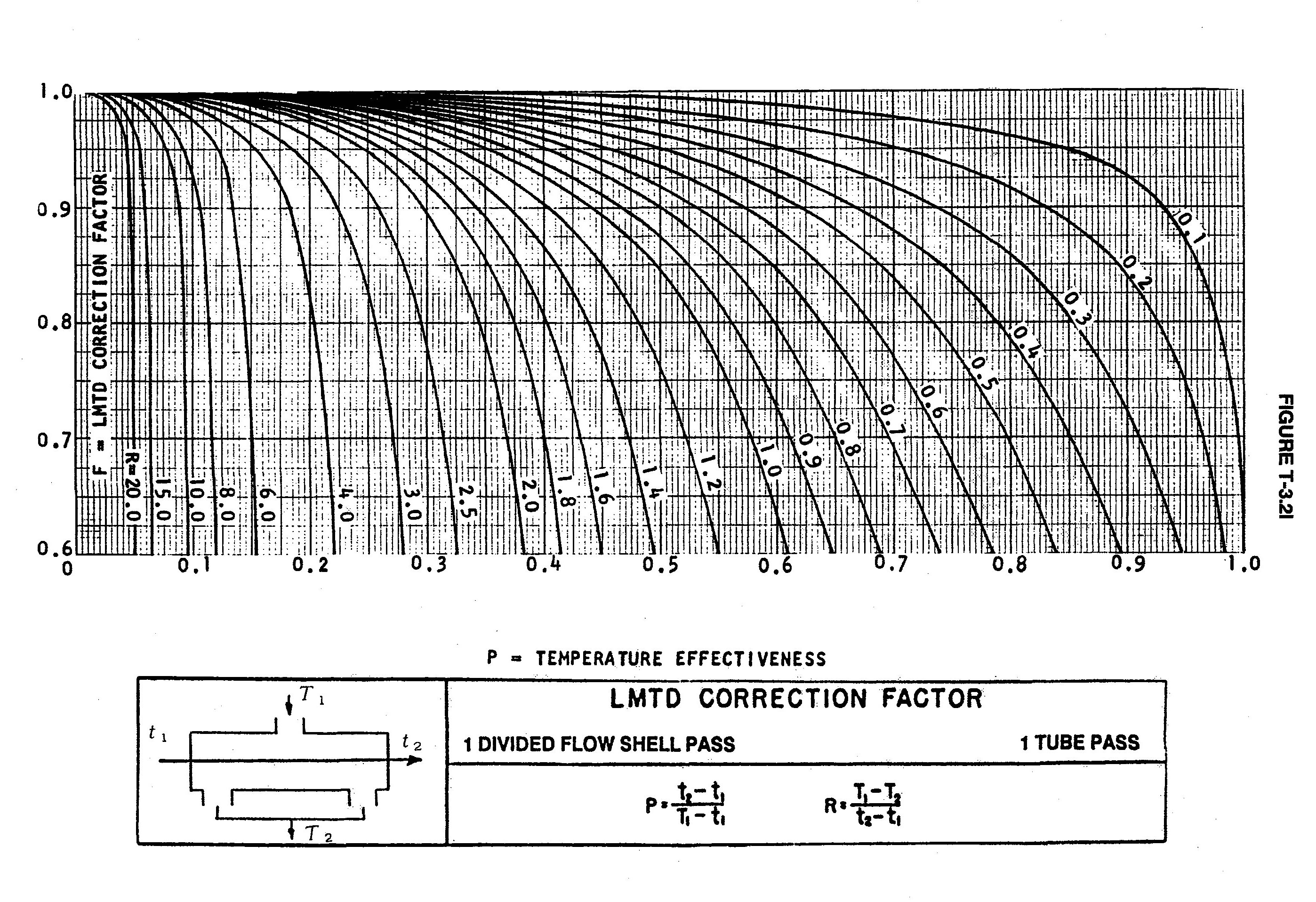
- 1 shell pass (divided flow) and 1 tube pass:
- 1 shell pass( divided flow) and even number of tube passes:

- 1 shell pass (divided flow) and 2 tube passes:

- 1 shell pass (divided flow) and 4 or multiple of 4 tube passes :

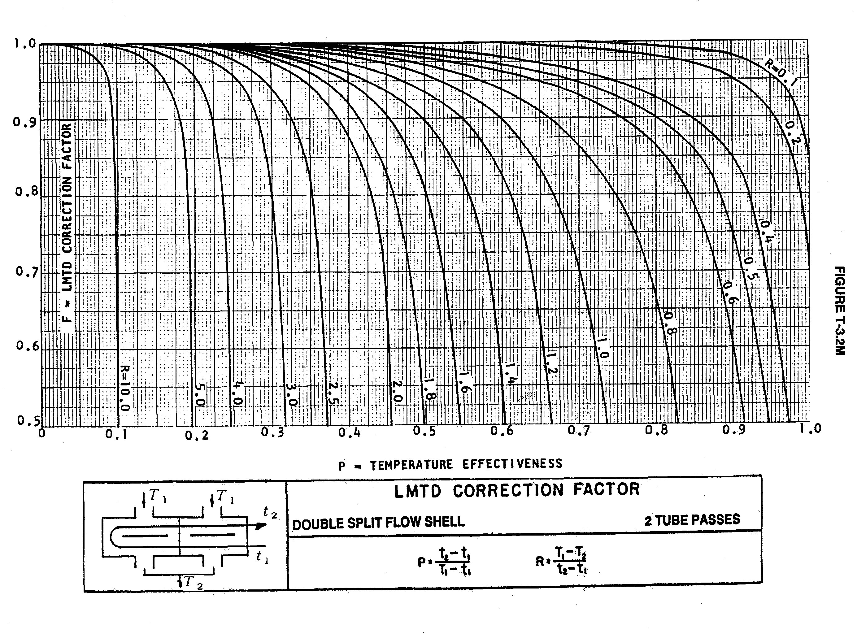
- 1 shell pass (double split flow) and 2 tube passes: